This page describes adding DCC sound to a new production SW-9/NW-2. These have speakers already installed, making the installation pretty much plug-and-play (or at least solder-and-sound!). The process is similar on the older SW-9s, but you need to find a spot for a speaker. The article on installing DCC sound in an SW-1 will give you some good ideas.
The plan for the current run of SW-9/NW-2 locomotives (starting with the 2005 Christmas MEC SW-9) was to ship them with an installed SoundTraxx Tsunami sound decoder, which includes motor control and lights. Unfortunately the Tsunami still doesn't have a firm ship date, so the interim solution is to install a Lenz Gold-JST decoder to control the motor and lights, and a SoundTraxx DSX sound-only decoder for sound. This makes the installation a little more complex, but gives a first rate installation available now.
The first step is to install the Lenz Gold-JST decoder. This is straightforward, and is documented here.
The first step in adding the SoundTraxx DSX decoder is to move the Lenz Gold-JST to a new position on the loco main pc board.
On the MEC Christmas loco, I have an adapter board. I insulated the adapter with a piece of electrical tape.
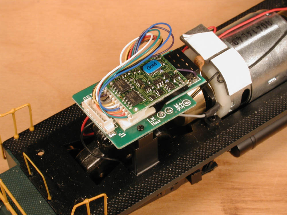
Then I used a small piece od 1/2" wide double-sided foam tape to mount the decoder. Make sure there is no chance that components on the decoder can touch any metal on the loco.
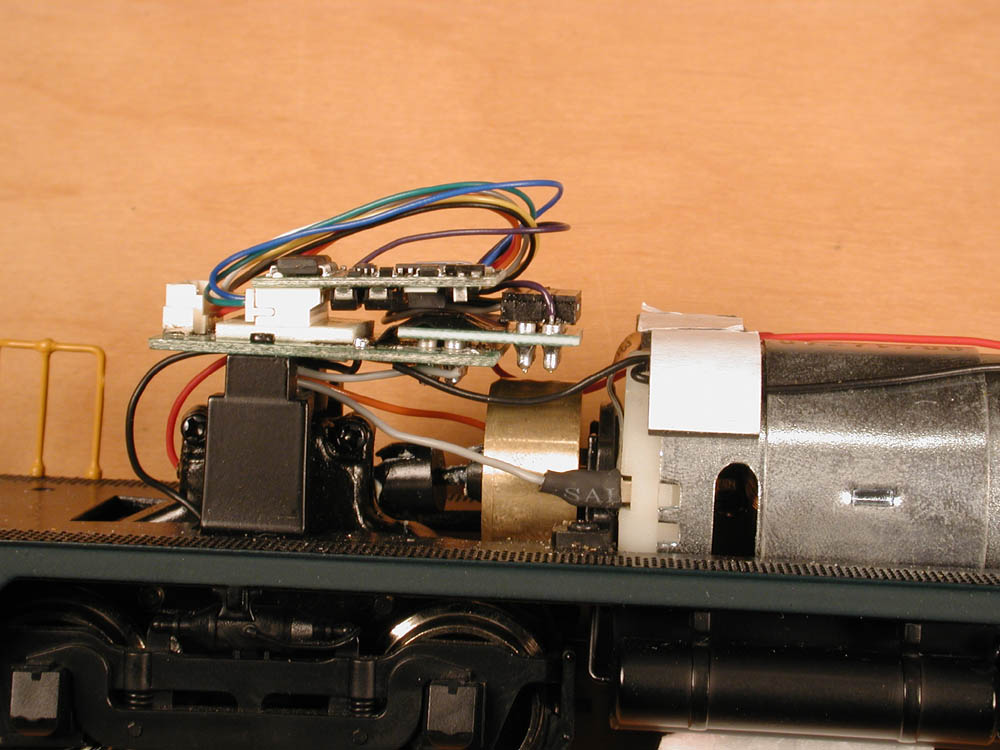
Here's a view from the side. There is enough room to mount the decoder securely and with no chance of any metal on the decoder touching any part of the locomotive. Just take your time, and try to make it neat. Make sure you don't cover the socket for the plug from the body.
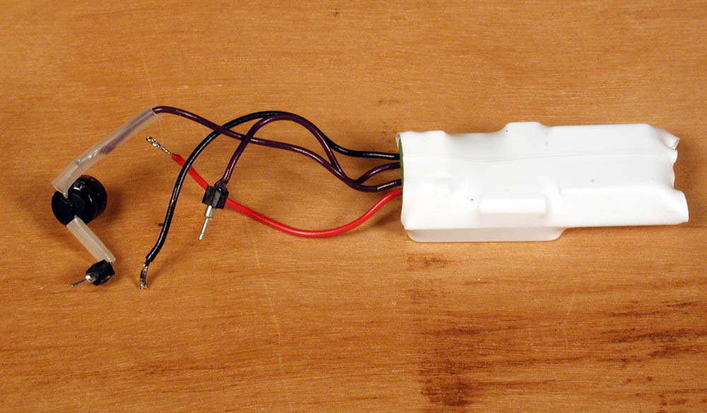
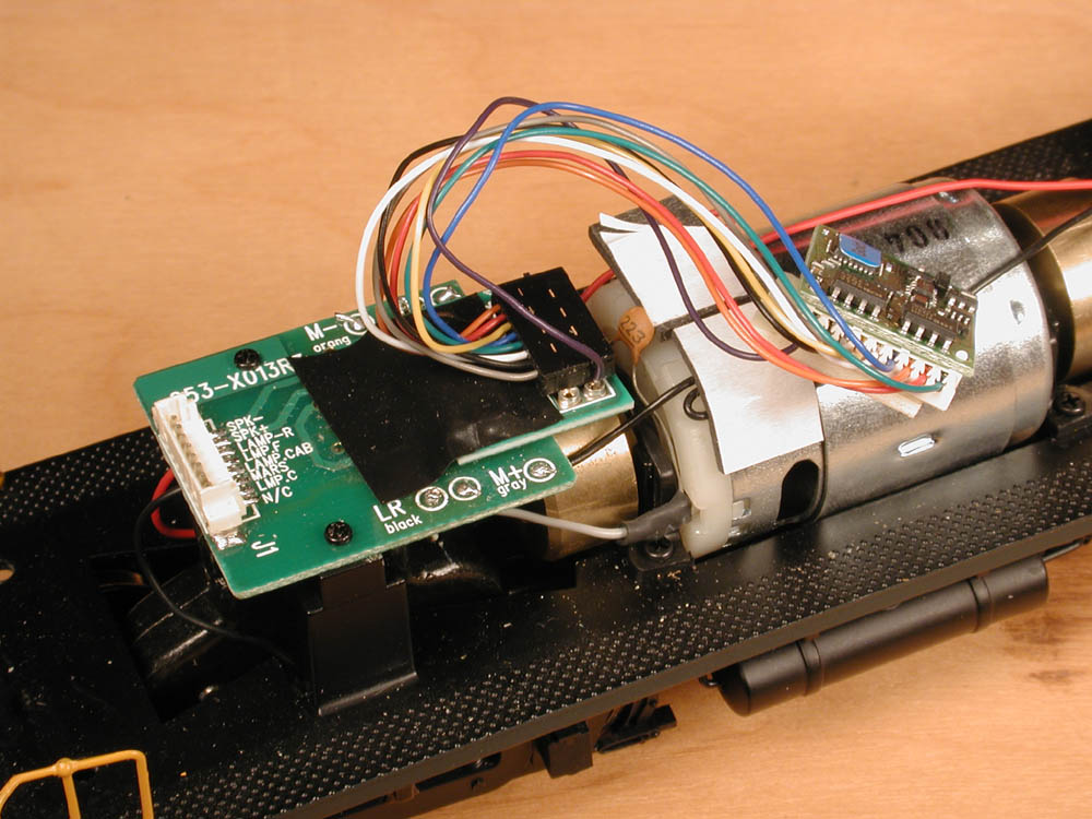
Here is the SoundTraxx DSX sound decoder. There are only 4 wires: Red and black are for power and connect to the red and black solder pads on the loco pc board. The two violet wires go to the speakers, and connect to pins 9 and 10 on the loco pc board socket. To prepare it for installation I cut the wires to about 3" long, stripped 1/4" of the insulation off each wire, and tinned them with a little solder. The violet wire next to the black wire needs to have the supplied capacitor soldered to it. I put a 1" piece of shrink wrap on the wire first, than slid it over the bare wire on the capacitor for insulation. The photo shows small pins soldered to the other lead on the capacitor and the other violet wire. These turned out not to fit, so just ignore them.
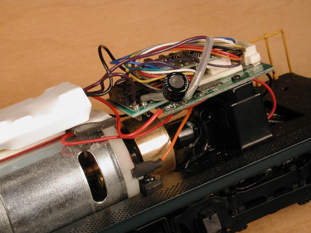
The DSX is mounted on a piece of double-sided foam tape on the motor. The red wire is soldered to the "RR Red" solder pad on the loco PC board. The violet wire and the lead from the capacitor are plugged into pins 9 and 10 on the socket. In this case, both wires seemed secure just pushed into the socket, so I did not solder them. To be sure, you could just touch them with the iron.
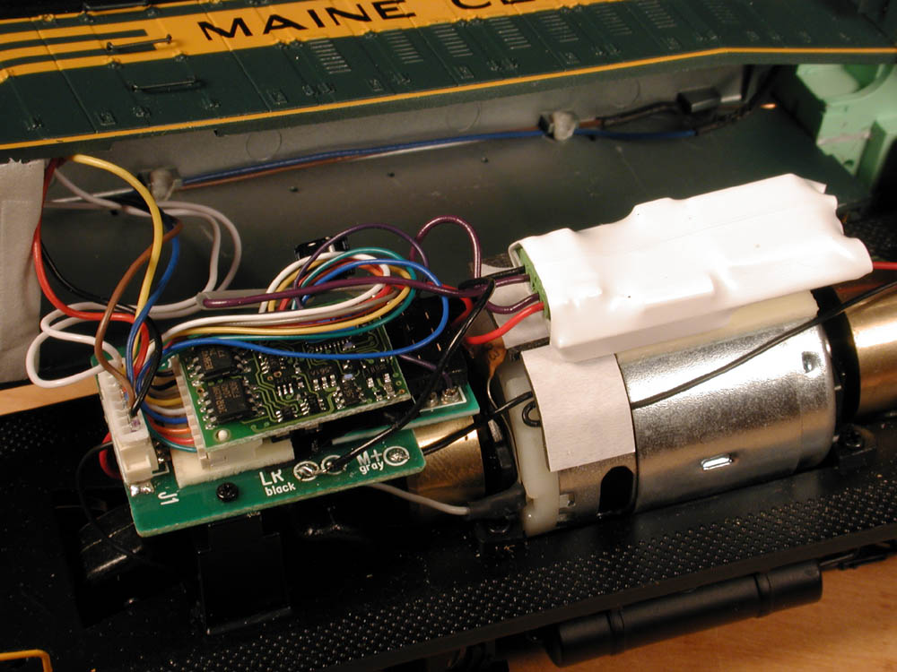
Here is the left side, showing where the black wire connects to the "LR Black" terminal on the loco PC board. Before connecting the black wire, however, we need to do some preliminary programming.
The one complication caused by using two decoders in the same loco is programming. My approach is to set the short address of the drive decoder (Lenz Gold-JST) to short address 3, and the short address for the sound decoder (SoundTraxx DSX) to short address 4. The long address of both decoders will be set to the locomotive road number. This all needs to be done one decoder at a time on the programming track. The effect is that both decoders respond to the same long address during operation, but each decoder can be programmed separately on the main line by using the short address. If this doesn't make sense to you, click here for more detail.
Right now, the Gold-JST is fully connected through the locomotive wheels, but the DSX is only connected to power on the right side (red wire). The black wire for the DSX is still disconnected. I use alligator clips to connect the programming leads from my command station to a short piece of programming track. If I connect both leads to the track, I'll program only the Gold-JST. If I disconnect the left rail lead and connect it to the DSX black wire, I'll only program the DSX.
Here's the programming for the SW-9:
Lenz Gold-JST (both leads connected to programming track)
| ? | CV | Setting | Description |
| Short address | 1 | 3 (default) | Used for programming on main line |
| Long Address | see note | Loco number (in this case 335) | This is the address both decoders will respond to in operation |
| Output D on F2 off | 36 | 0 | default for the Gold-JST is F2 controls output D (cab light). As we want F2 for the bell, we need to shut this off |
| Output D on F6 on | 40 | 8 | F6 will operate the cab light |
| Switching Speed Function on | 58 | 15 | F5 will turn on switching speed function (halve the spped table for precise low speed switching) |
SoundTraxx DSX (left rail connected to programming lead, other lead to black wire on DSX)
| ? | CV | Setting | Description |
| Short address | 1 | 4 | Used for programming on main line |
| Long Address | see note | Loco number (in this case 335) | This is the address both decoders will respond to in operation |
| Dynamic brake | 38 | 8 | Dynamic brake sound not affected by F4 |
| Dynamic brake | 41 | 8 | Dynamic brake sound on F7 |
You'll need to plug the cable from the loco body in to allow the DSX to respond to programming.
OK, now that the initial programming is done, connect the black wire from the DSX to the LR Black pad on the loco PC board, place the body back on the loco and test it. You are all done! Here are the functions now:
| F0 | Head and rear lights, direction dependent |
| F1 | Bell |
| F2 | Horn |
| F3 | Coupler clank |
| F4 | Disable acceleration and braking delay |
| F5 | Switching Speed function (halves speed table for precise low speed switching. |
| F6 | Cab Light |
| F7 | Dynamic brake |
| F8 | Mute |
This was complicated to write about, but only took me about 20 minutes to do. The entire job, including taking the loco apart, removing the AC/DC board, installing both decoders, programming, and reassembling, takes about an hour after you have done it once.
If anything is not clear, or you have suggestions on improving this document, please let me know!