The Lenz Gold-JST is the perfect decoder to bring out the best in an already fantastic running locomotive. The specs are posted elsewhere in detail, but the short and sweet is that the Gold-JST is a SILENT decoder (no buzz at low speed) with fully adjustable load compensation (no more slowing down around curves, or where track voltage is down because you need another drop), with a switching mode (F4 cuts the speed table in half, to allow extremely precise motor control for switching). There are a bunch more important features, but the bottom line is that you will LOVE this decoder! Lets get started installing it in your new SW-9/NW-2!
By the way, if you haven't ordered your SW-9/NW-2 yet, you can get it from SHS with the decoder already installed!
Click on any photo for full size.
1. First step is to test the locomotive with the DC shorting plug (or AC/DC board, whichever came in it). If you know there is no problem with the loco it makes any troubleshooting later on much easier. The loco should run fine on DC. Even this decoder won't fix dirty wheels or pickups!
2. Check to see which version SW-9 you have. The MEC Christmas SW-9, and maybe some others, have a "no DCC" sticker on the bottom of he loco, and on the PC (printed circuit) board (socket) inside the loco. These units need a replacement PC board with the correct pin placement for a DCC plug. If you have an SW-9 with the "no DCC" sticker, and you don't have the replacement board, let us know and we will send you one. Instructions are included here for installing it.
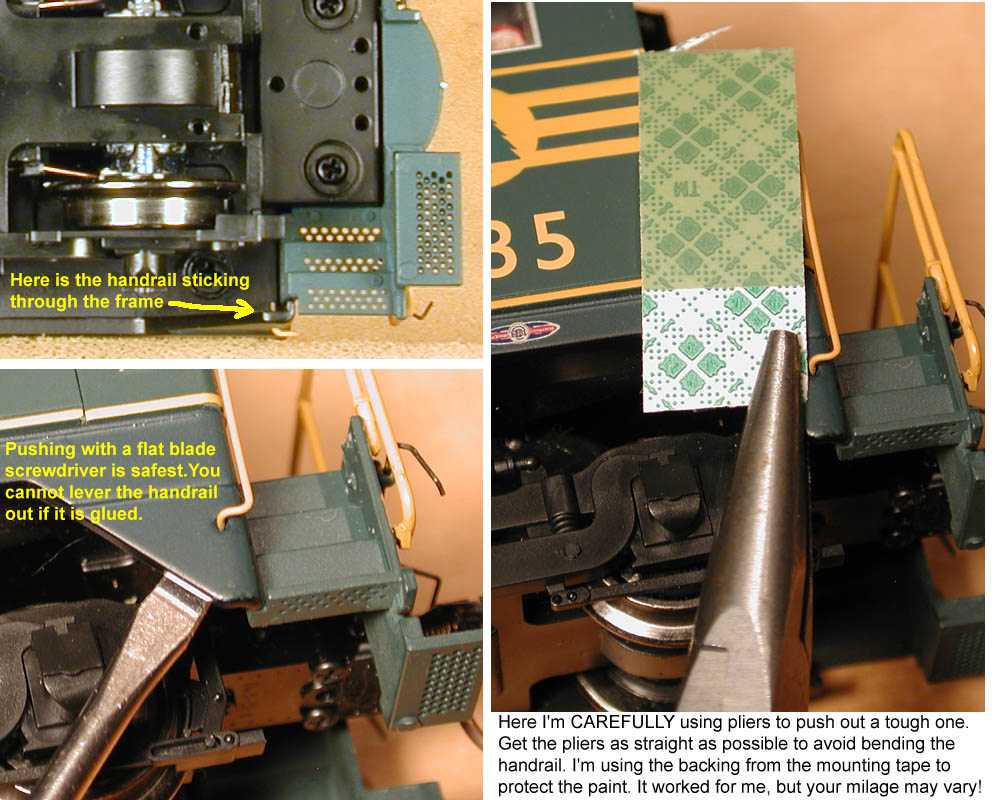
3. Carefully pull out the bottom end of the vertical handrail which goes between the shell and the frame. On my loco it was only glued at the top, so it popped out of the bottom easily. The latest SW-9/NW-2 seem to be firmly glued. I found the best way to get them out is push them out from inside the frame, using a flat screwdriver, or in tough cases using small needle-nosed pliers. Click the picture on the right to see more detail.

4. Place the loco on a soft surface, and remove the 4 body mounting screws. I used a Phillips screwdriver marked PH 000x40, and it seemed a good fit. The body should then easily lift off until you can reach the plugs inside.
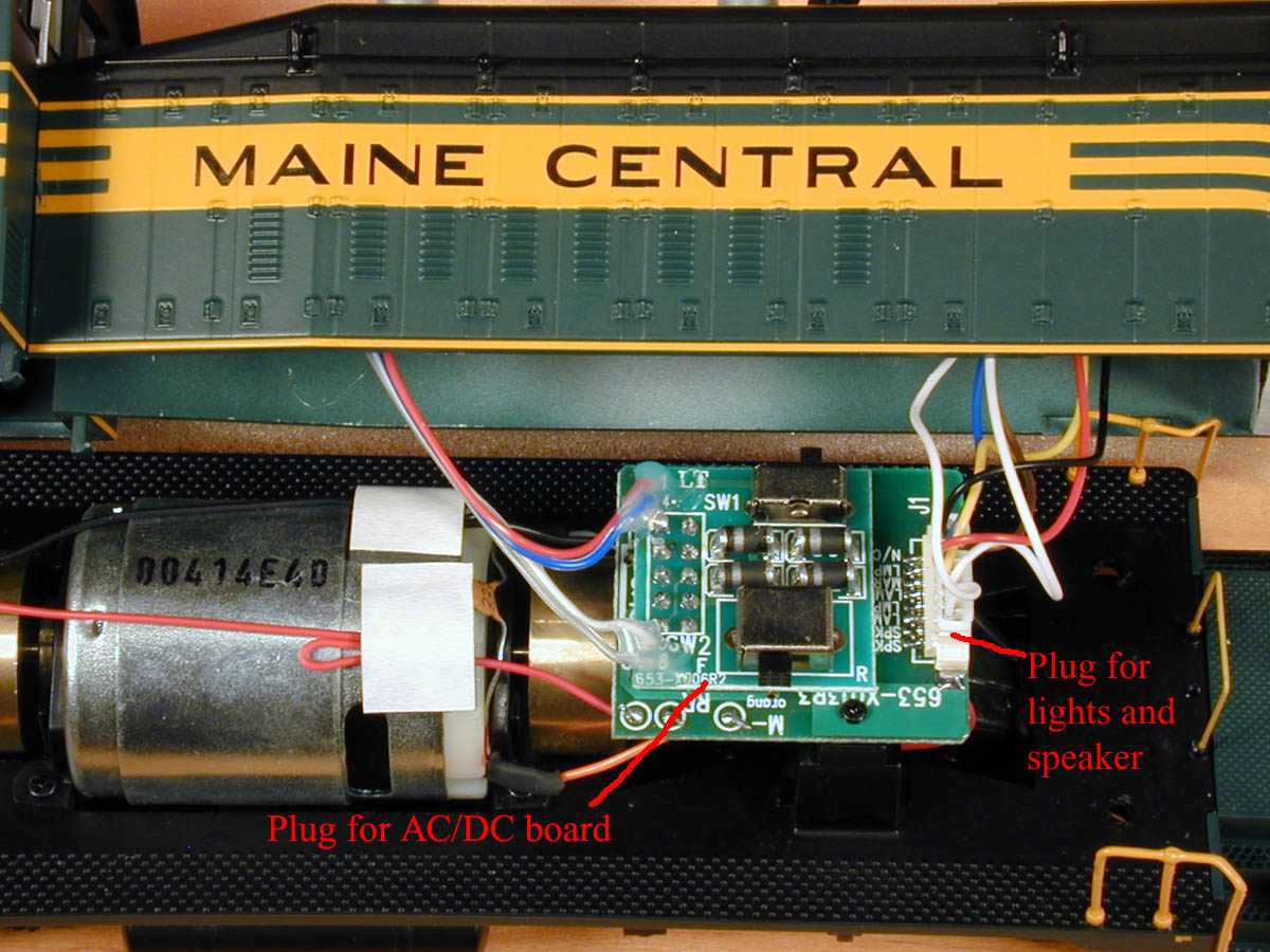
5. Depending which version of the SW-9 you bought, you may have a DC shorting plug, AC/DC board, or LocoMatic board installed. Unplug it, and remove whichever board you have. This picture shows the AC/DC board. I used a small flat blade screwdriver to gently lever the larger plug out, doing a little at a time from all four sides to keep it parallel to the socket board. The other plug cab be pulled straight out, but don't pull on the wires. Take your time and you won't bend any pins.
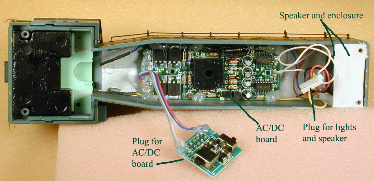
The AC/DC board is quite large, and is held in the shell with 4 or 5 big globs of hot glue. It comes out very easily with careful prying.
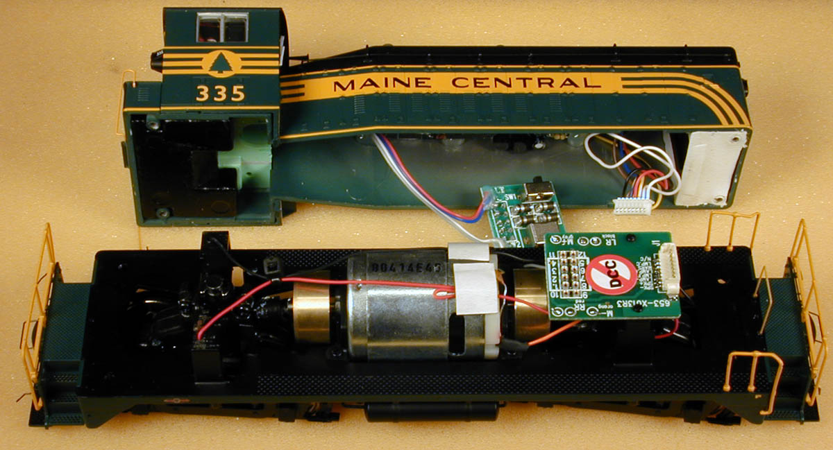
Here is the shell and chassis before removing the AC/DC board. Note the "no DCC" sticker on the pC board in the loco. That means that the pins in the socket are ordered incorrectly for DCC, and will require a replacement board before installing a DCC decoder. If your loco has the "No DCC" sticker, the instructions for swapping in the replacement board are here.
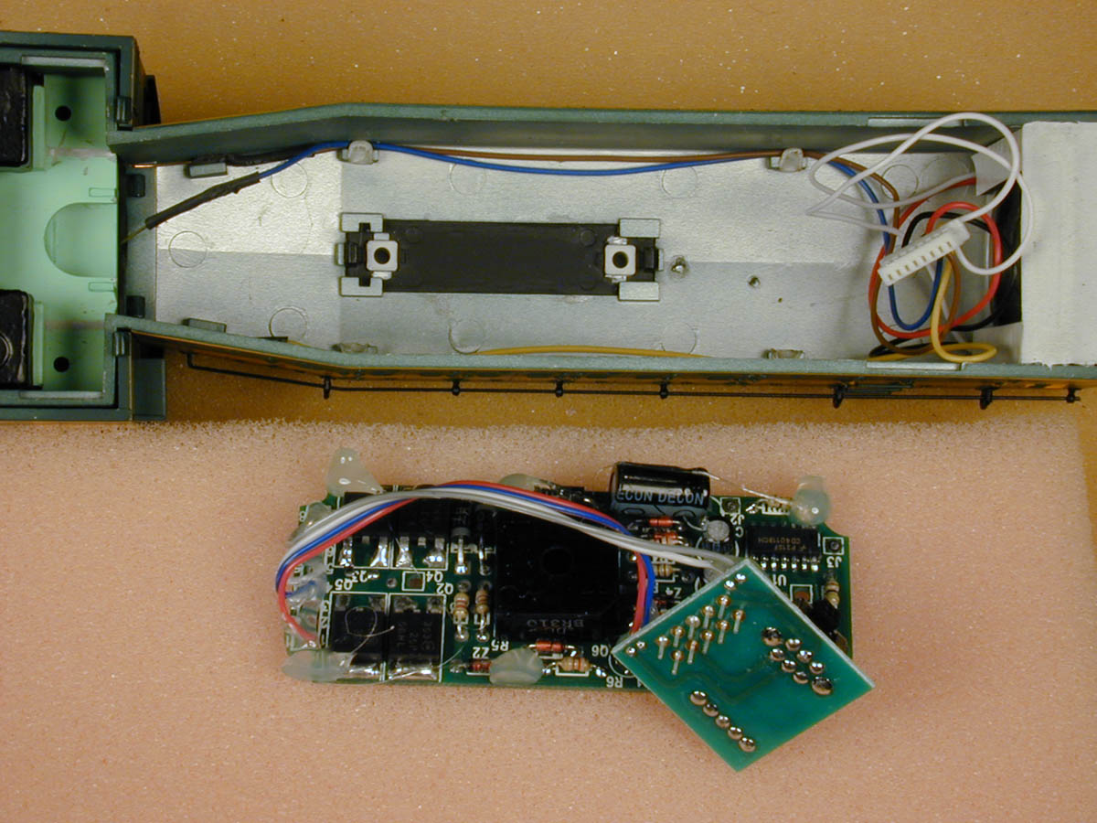
This is the shell after removing the AC/DC board.

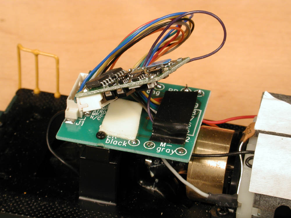
6. Plug the Gold-JST into the socket. Notice the orientation of the plug (wires point to the front of the loco) and be sure to plug it into pins 1-8 on the socket. That means there will be one empty row of sockets visible above and below the plug. There is one extra lead (wire) on the decoder. If your SW-9 has cab lights, plug that extra wire into pin 12. otherwise, insulate it with electrical tape and don't use it. I stripped about 1/4" of wire, and carefully tinned it with a soldering iron to stiffen it before inserting in the socket. You could also solder the wire to the socket. (This picture shows an experimental adapter board on top of the PC board. You'll be plugging directly into the socket on the PC board).
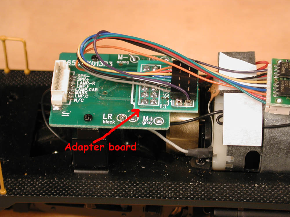
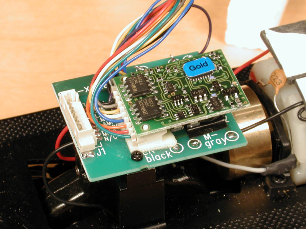
This picture shows the violet wire plugged in to pin 12. (Again, this you'll plug directly into the PC board socket).
7. I put a piece of electrical tape on top of the plug, and over pin 12. This is to ensure there will be no shorts, and it also makes the wire in pin 12 more secure. Use a piece of double-sided foam tape to secure the decoder to the PC board. Don't cover the socket for the plug from the shell. Be sure there is no way any components on the decoder can touch anything except the tape. If you are not going to install a sound decoder, you can mount the Gold-JST on the motor, where there is lots of room. I'm going to add sound, so I put it on the PC board out of the way.
8. Replace the body, after connecting the plug in the front of the loco. The installation is done! This took a while to photograph and write-up, but the actual installation was only 15 minutes! The loco is now ready to run, using address 03. The next article will discuss changing the address to match the locomotive number, and operation. If you want to add DCC sound to your SW-9/NW-2, go here.