This page documents upgrading the American Flyer Y-3 to support DCC.
The American Flyer Y-3 is one of me all time favorite AF locomotives! Here are links to the owner's manual and DCC addendum.
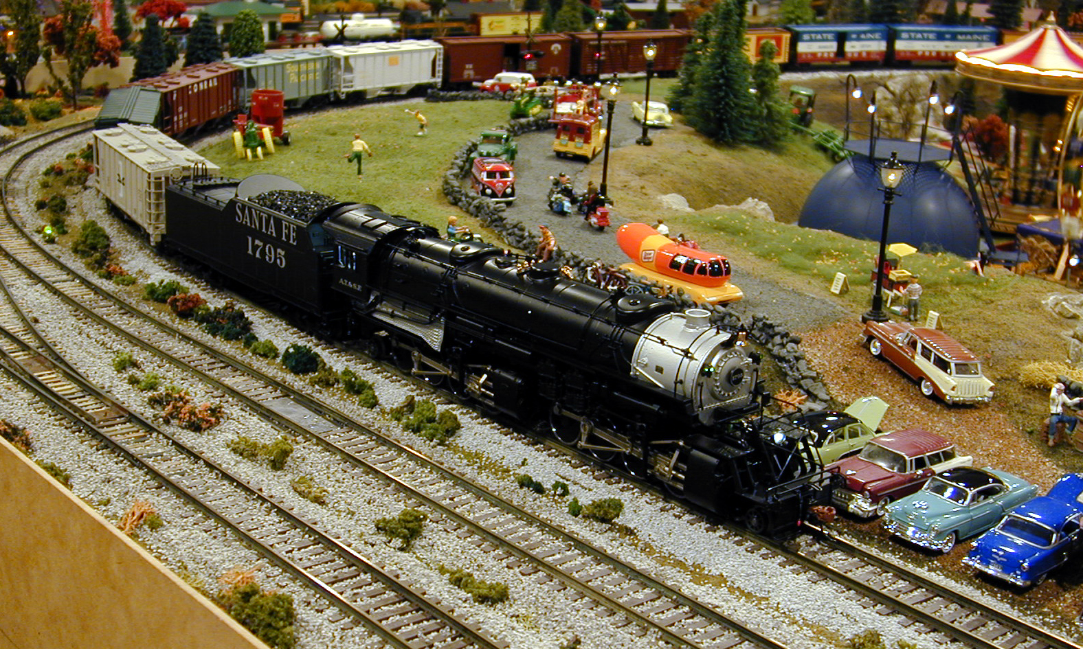
This is the process I used to upgrade the American Flyer Y-3 to DCC. The original boards that come in the loco include the hardware to support DCC, but the firmware installed by the factory support only Legacy, TMCC, and AC. The firmware to add DCC support was sent to me by Jon.The first step is to test the loco. This loco worked perfectly on both TMCC and AC before I started the upgrade
There are 5 screws holding the shell to the chassis, all the same size. One is under the firebox cover.
Two under the cab
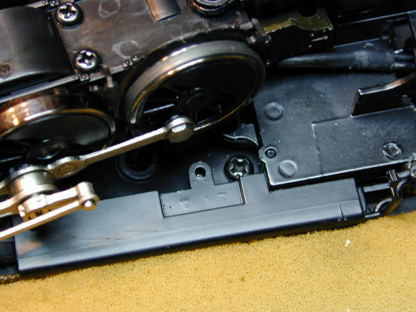
And two between the driver sets.
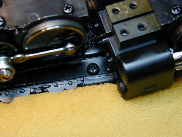
I removed the steam pipe fitting shown here. Just one screw and it lifts right off.
The shell should lift off pretty easily. I had to lift the shell slightly from the rear, then backwards just a touch as it lifted out. There are several wires going from the chassis to the shell, so keep it close and don't strain them. I don't recommend disconnecting the wires if you can avoid it.
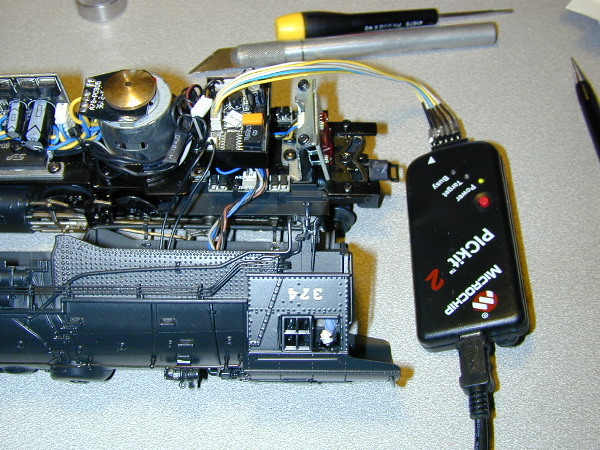
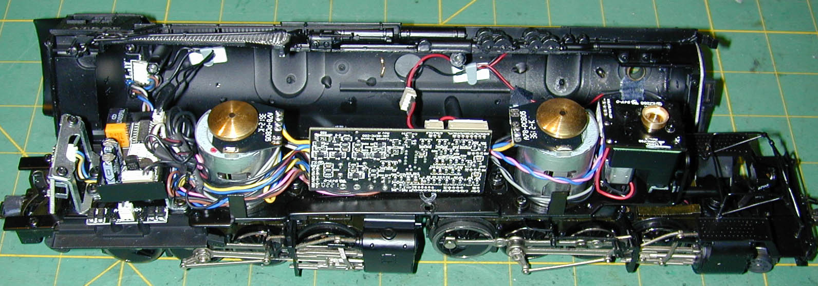
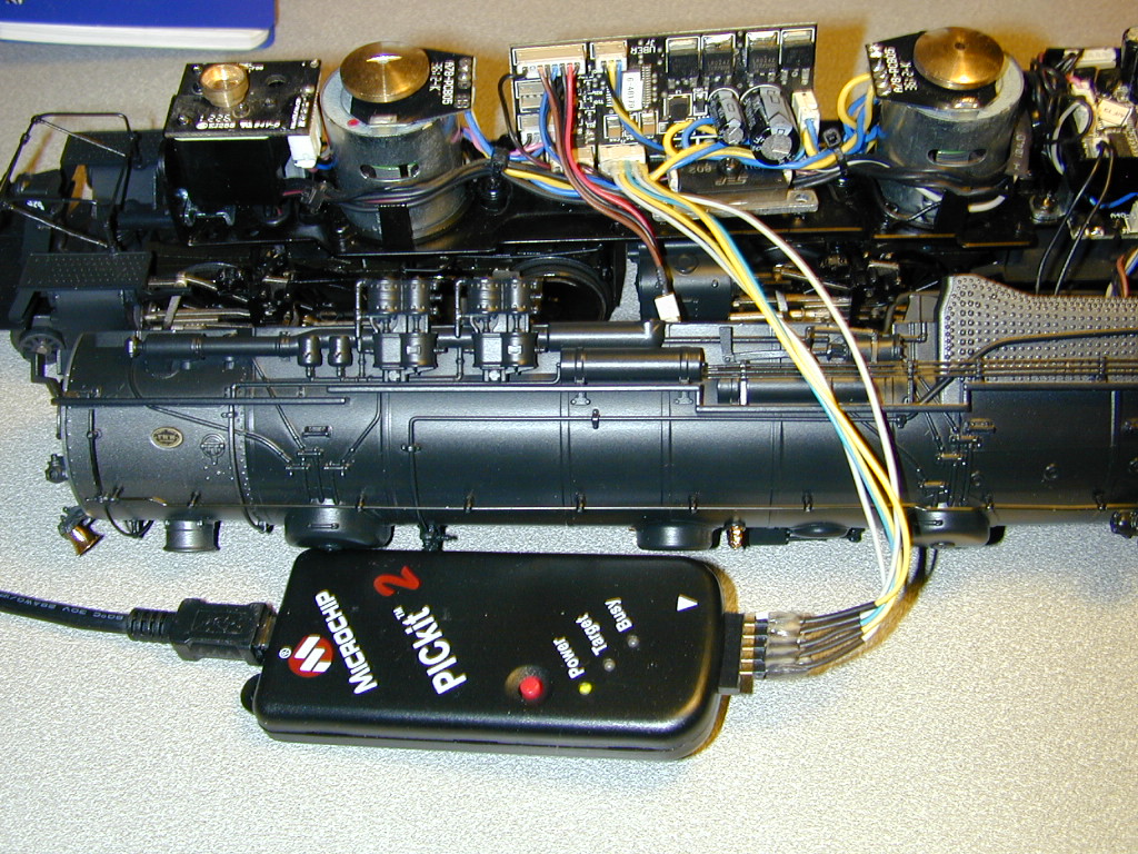
This is the radio board. Remove the plug from the board carefully, without putting strain on the wires. I use an Xacto between the plug and the socket to get it started, then a small screwdriver to remove the plug the rest of the way.Plug the PICkit 2 cable into the socket on the board, being careful to check pin orientation. After plugging in the cable, connect the USB cable to the PC, then start PICkit 2 v2.61.
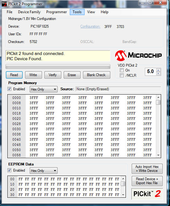
This is the startup screen. Notice that a PICkit 2 has been found and connected, and that a PIC device has been found. The device is shown as a Midrange/1.8 V Min Configuration and is a PIC16F1825. These are all correct for the radio board. If the config is not shown as Midrande.1.8V minimum, select that from device family. Also, check under the tools menu, and if "FastProgramming" is checked, turn it off.
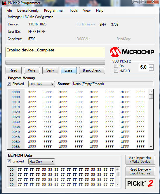
Erase the device.
File/Import Hex.
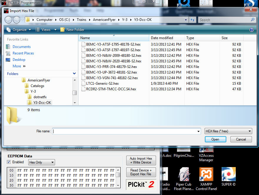
Select the file RCDR2-STM-TMCC-DCC.S4.hex
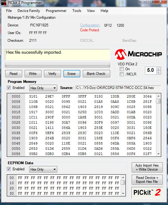
PICkit 2 reports Hex file successfully imported. Click Write to write to the device.
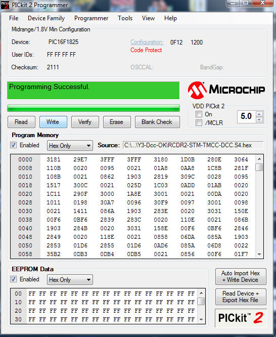
Device will program and verify. At this point, unplug the USB cable, unplug the PICkit 2 cable from the radio board, and plug the cable you originally removed back in. This completes the radio board upgrade.
This is the motor control board. The board is normally mounted such that it leans in, making it impossible to get at the plug. Bend the board back carefully to vertical (you are just bending the mounting wires of the bridge, which is not an issue). If you prefer you can remove the screws from the heat sink to allow easier access to the plug. Remove the plug from the board carefully, without putting strain on the wires. Plug the PICkit 2 cable into the socket on the board, being careful to check pin orientation. After plugging in the cable, connect the USB cable to the PC, then start PICkit 2 v2.61.
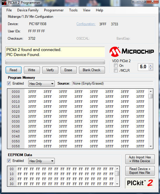
This is the startup screen. Notice that a PICkit 2 has been found and connected, and that a PIC device has been found. The device is shown as a Midrange/1.8 V Min Configuration and is a PIC16F1938. These are all correct for the BEMC board. If the config is not shown as Midrande.1.8V minimum, select that from device family.
Erase the device.
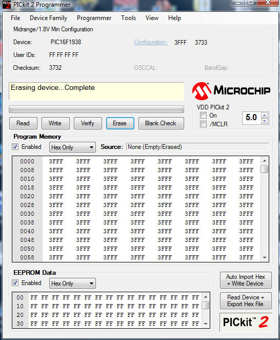
PICkit 2 reports Erasing Complete.
File/Import Hex.

Select the file that matches your loco. I'm using BEMC-Y3-UP-3672-48181-S2.hex
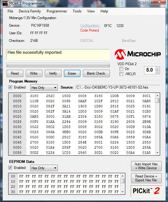
PICkit 2 reports Hex file successfully imported. Click Write to write to the device.
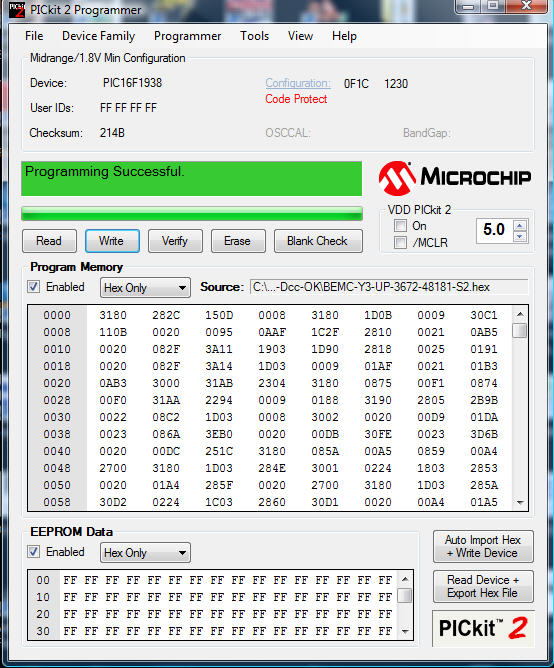
Device will program and verify. At this point, unplug the USB cable, unplug the PICkit 2 cable from the BEMC board, and plug the cable you originally removed back in. Bend the board forward to its original position, or retighten the heat sync if you loosened it, being careful not to trap wires under it. This completes the motor control board upgrade.
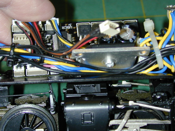
Here's the potential problem with removing the heat sink. You can see that several wires run under the heat sink, and there is a sharp edge around the hole that the screw holding the bridge rectifier goes through. If you aren't extremely careful you can pinch a wire under that edge. I've done it twice! Now I just bend the board to a vertical orientation, as described above.
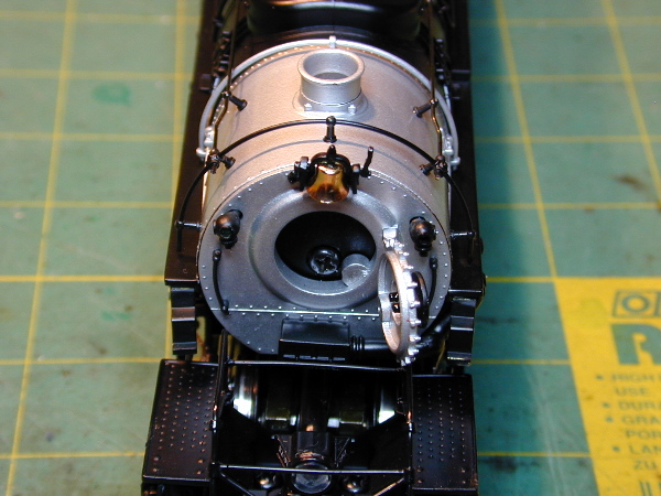
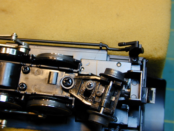
When reassembling, make sure that the smoke unit is lined up. After fitting the chassis into the shell, but before using any force on the front of the shell, check that the smoke unit is centered in the stack. I used a small screwdriver to move the smoke unit slightly until the shell dropped on.
The tender only needs to be done for DC. If you want the sounds to work correctly on DC, upgrade the firmware in the tender.There are 6 screws holding the body onto the chassis.

The routine is the same as the other boards:


Reassemble, the tender, test everything, and you are good to go!