Start by removing the chassis from the boiler. I always unscrew the smoke stack pipe to avoid damaging it.It is already removed in this picture.

Next, the smoke switch in the cab needs to be detached to allow the boiler to come off. Remove the 2 small screws at the bottom.
You need to remove the pilot to get at the fromt mounting screws. Remove the 2 small screws and carefully lift the pilot off the gaurd wires.

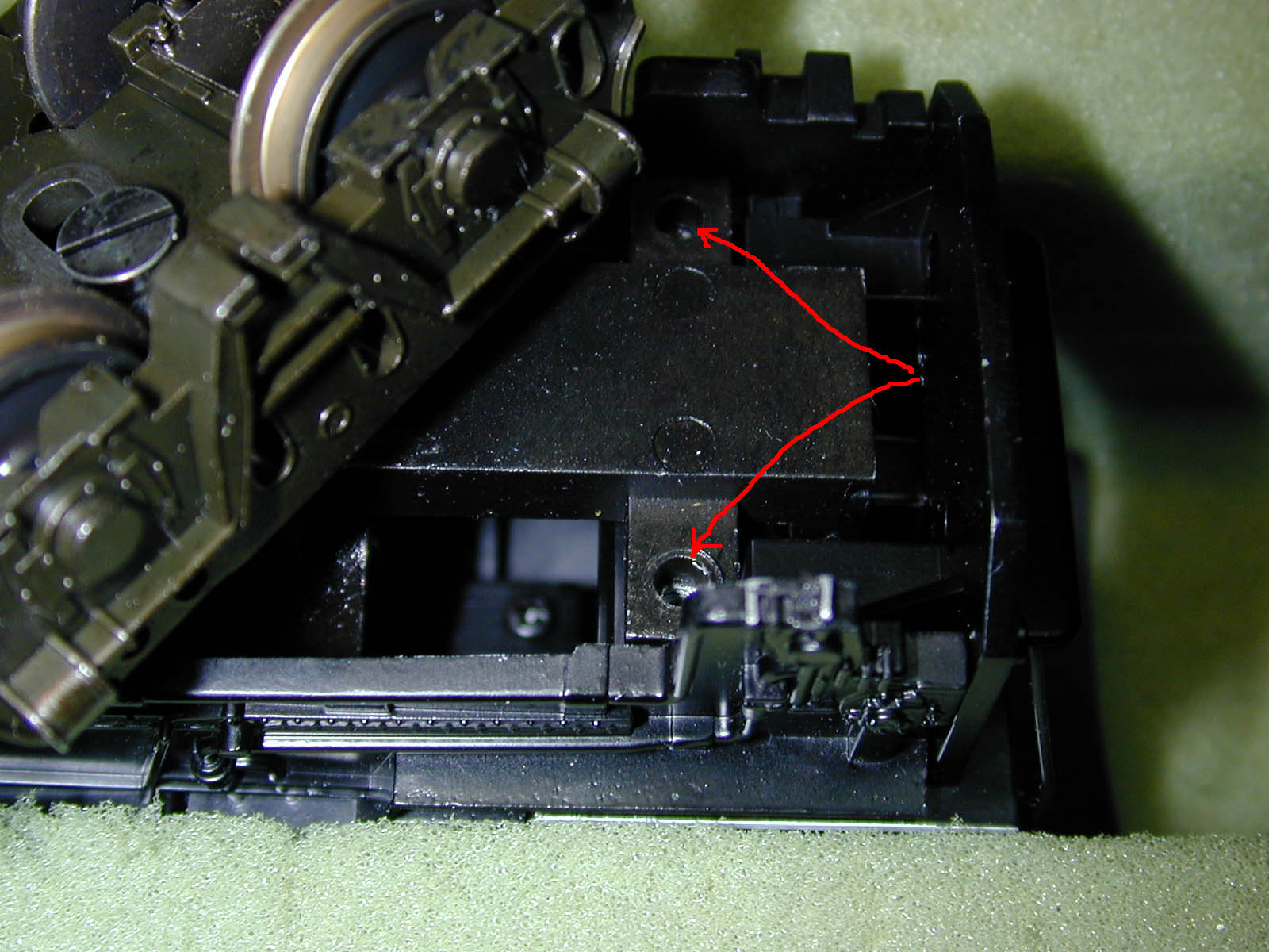
Now you can remove the two front mounting screws.
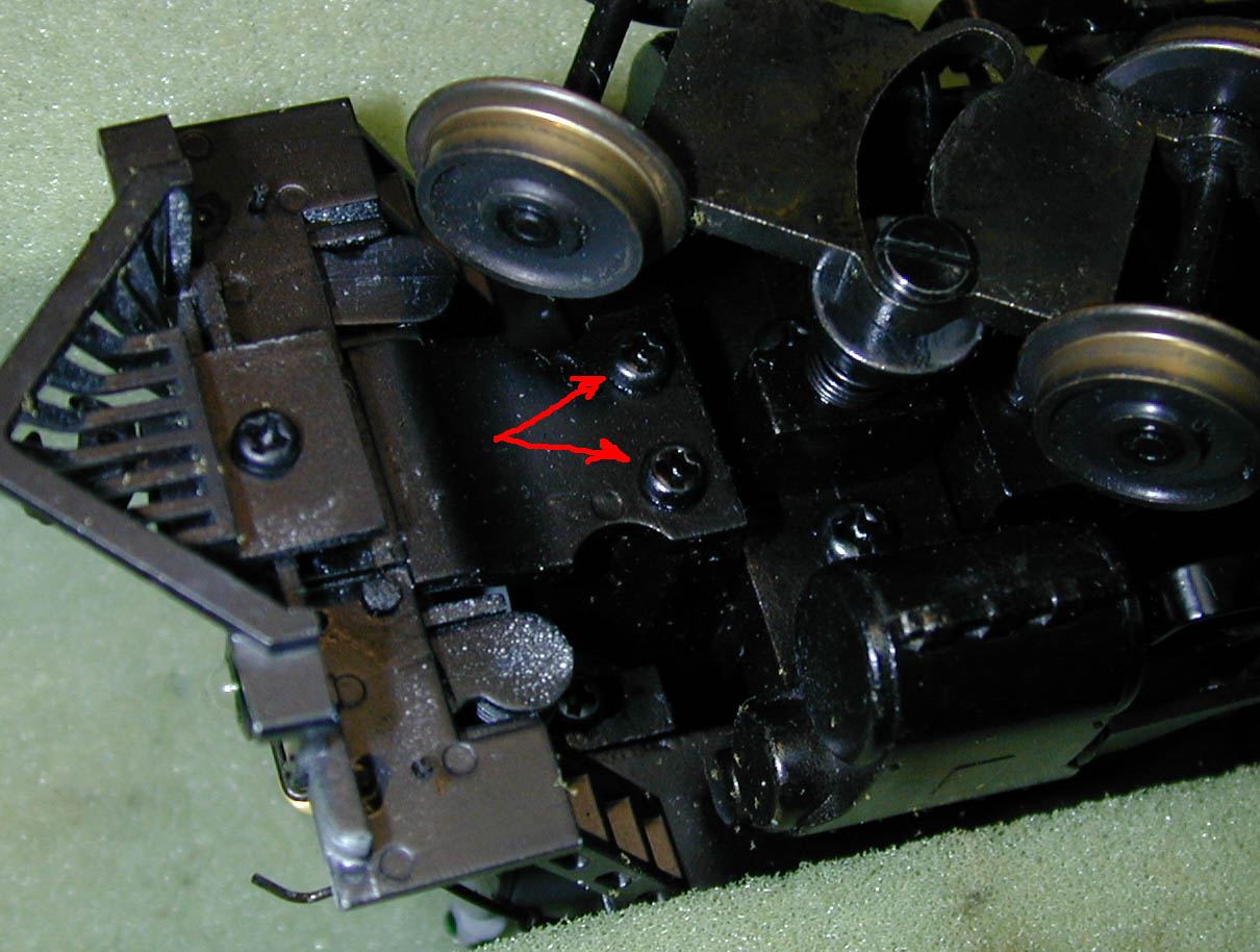
Finally, remove the 2 rear mounting screws under the cab. The chassis will lift straight out. Be careful not to stretch the headlight wires. There is a plug in the headlight wire secured with clear tape. Remove the tape and unplug the headlight. Put the boiler aside.
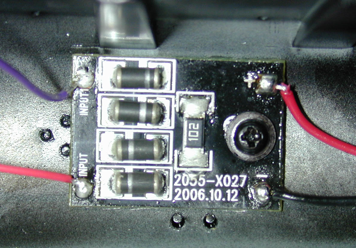
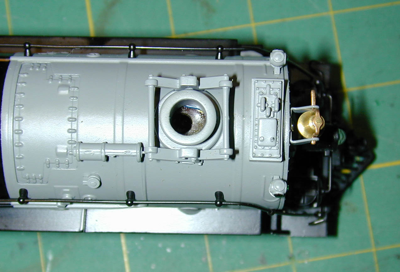
[Note: on the latest Northern, the headlight is an LED. There is a small PCB with diodes and a resistor in the headlight wire, screwed to the top of the boiler. I removed it and replaced it with a 1200 ohm resistor, to save a little room.]
The 2 rear mounting screws are the largest. The front mounting screws are the same tread as the screws that hold the pilot, but longer.
Here's the chassis from the older version, with an incandescent headlight.
This is the chassis from a unit with the LED headlight, after the wires are removed from the small PCB (they are the red and black wires sticking up).
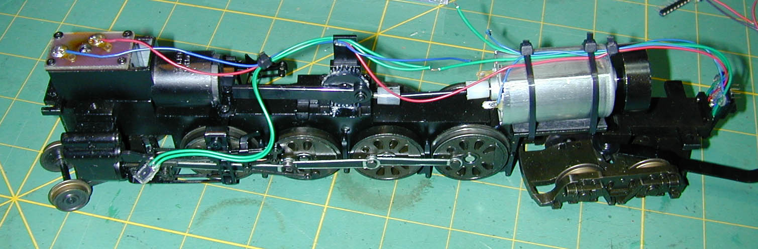
To mount the Tsunami in the loco. I made a shelf 1 1/4" long by 5/8" wide outside by 5/8 high inside out of 1/8" balsa sheet. You could use styrene if you prefer.. Glue it to the frame between the motor and gear tower as shown. I use 5 minute epoxy, or Goo. Clean the surface of the loco where you will be gluing with alcohol.

Remove the blue wires from the motor terminals. Cut the green wires as shown, about 1" after the cable wrap on the motor. Mount the Tsunami as shown, using either Goo or double-sided foam tape. Mount the Tsunami offset to the right 1/16" or so to allow soldering to the terminal on the relay. Mount the relay as shown with a drop of CA at each end.
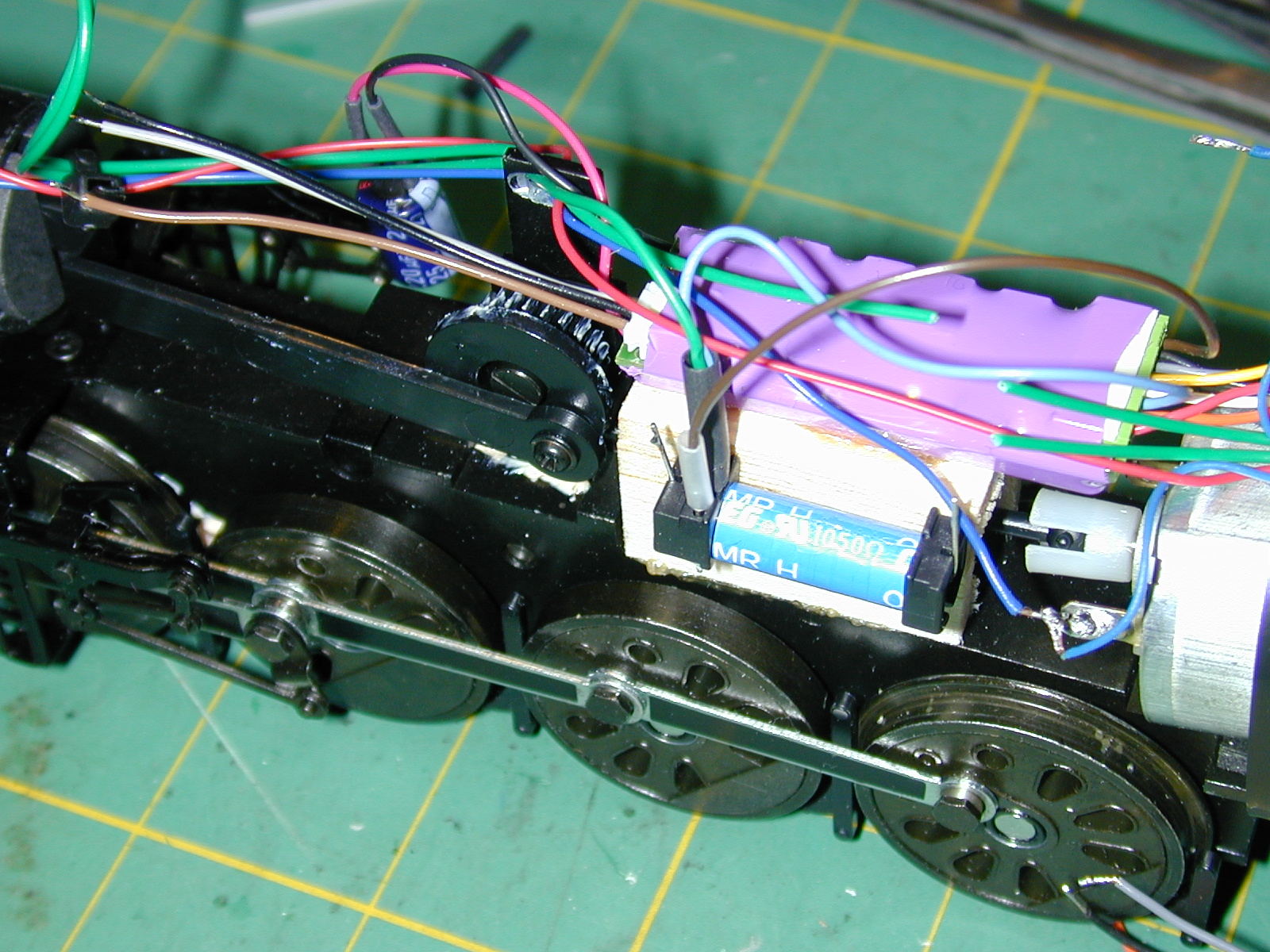
The relay will be used to control the smoke unit. Connect the Tsunami blue wire (Function Common) to either green wire going to the headlight.
[Note: If you have the LED version, remove the small PCB board in the top of the boiler. Cut the red wire going to the LED headlight in the middle, and solder a 1200 ohm resistor into the wire. You now have a black wire and a red wire (with the 1200 ohm resistor in it) coming from the headlight. Connect the Tsunami Blue wire to the red wire, then continue below.]
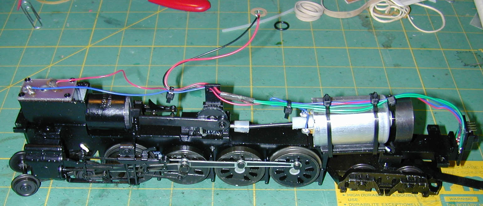
Connect the combination of the Tsunami blue and the headlight wire to one coil terminal on the relay. Use shrinkwrap. Then connect the brown Tsunami function lead to the other side of the relay coil.
Connect the Tsunami white lead to the other headlight wire.
Connect the Blue wire from the smoke unit to a switched lead of the relay.
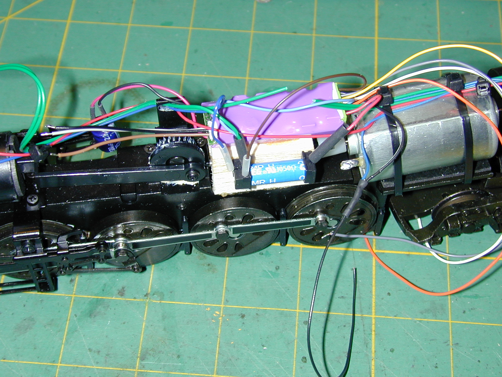
[I number the pins on the loco switch/plug 1-4, left to right, looking at the rear of the loco. Pins 1 and 4 go to green wires, these will be for the speaker. Pin 2 goes to a blue wire, and to the red wire through the smoke switch. Pin 3 goes to the othe blue wire.]
Twist the blue wire from Pin 3 of the loco/tender connection and the Tsunami red wire together, and connect them both to the other switched contact on the relay.
Pin 2 is a blue wire, the one that goes to the red smoke wire through the switch. Connect this wire to the Tsunami black lead, along with a short (4") wire which will go to the smoke sync switch. Protect with shrink wrap.
Connect Tsunami Orange to the left side motor terminal, Tsunami Grey to the right side motor terminal. If you want, you can put a 1 A fuse in the orange wire. Put it in a piece of shrinkwrap, and lightly glue it up under the relay. I've stopped doing this, as the Tsunami seems to be capable of handling the Northern without any problem. I've yet to burn out a Tsunami!
Pins 1-4. Pins 1 and 4 will be the speaker wires. Connect the two green wires from pins 1 and 4 of the locomotive plug to the two violet speaker wires from the Tsunami. Use shrink wrap.
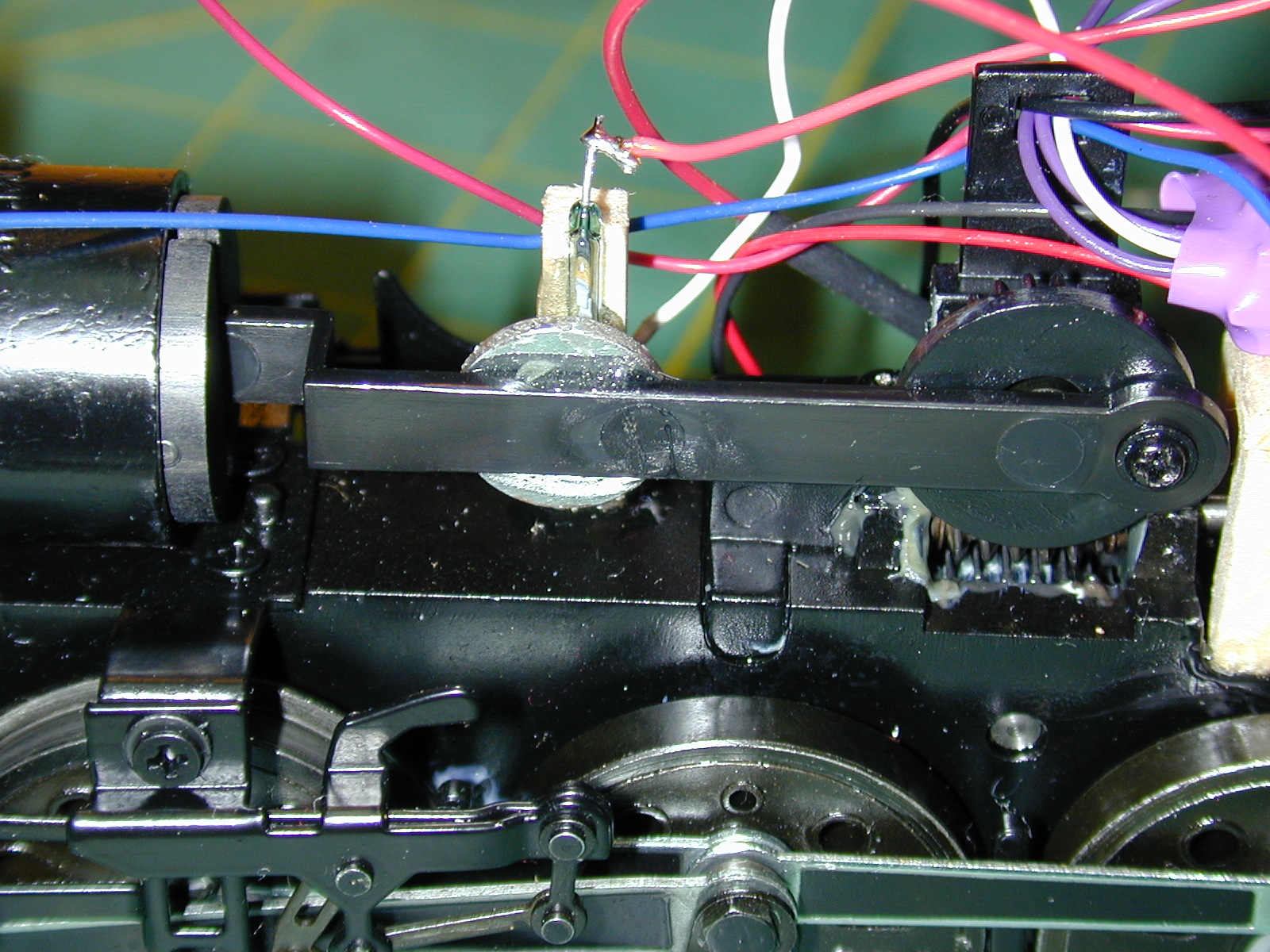
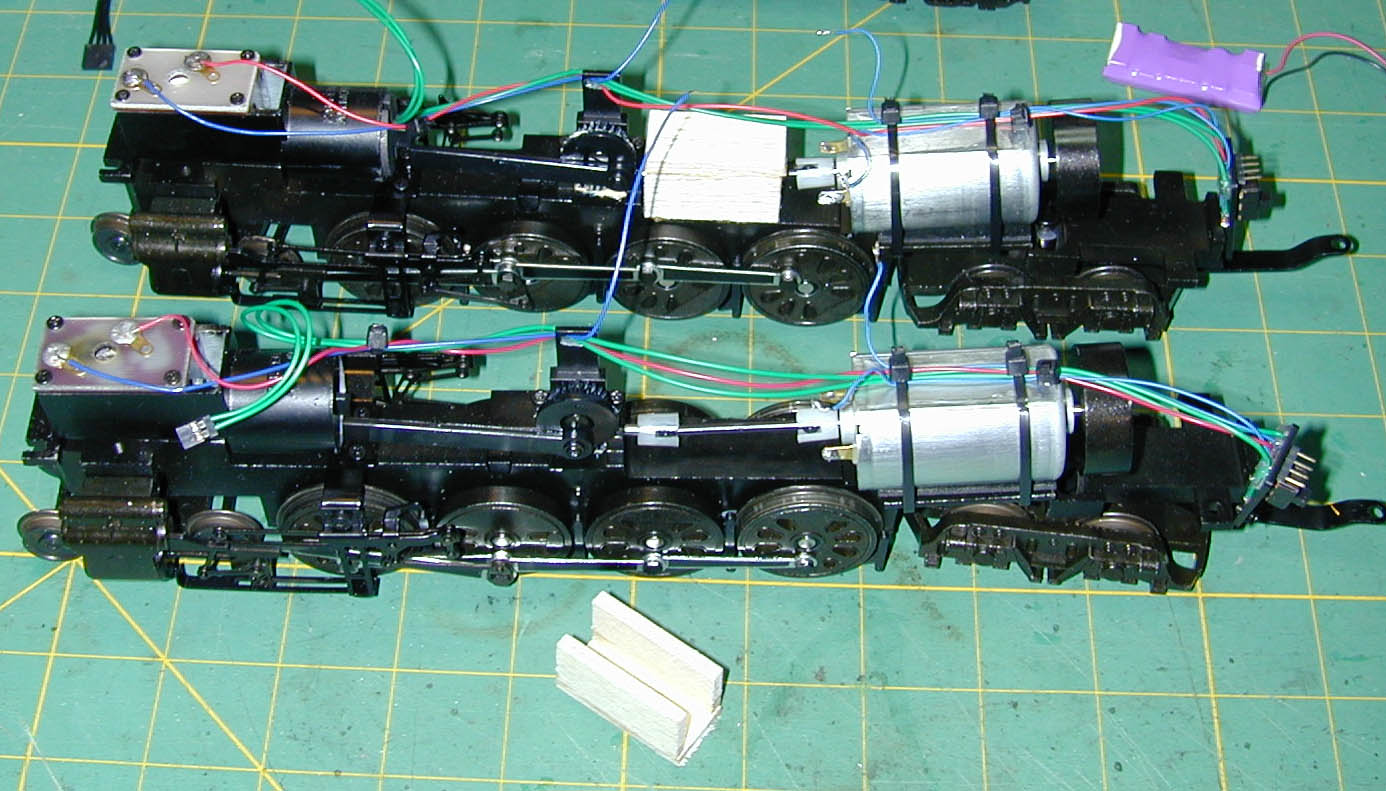
Add a lever or magnetic switch for the chuff sync. In this case I used a Mimiatronics magnetic switch. The magnet is epoxied to the connecting rod of the smoke piston. The reed switch is epoxied to a mount made out of some balsa. Each time the piston pushed smoke out the reed switch will open, causing a chuff from the Tsunami.
Here's another view of the switch and magnet. Place the balsa back against the step in the chassis (as close as possible to the gear). Mount the magnet so that it is opposite the switch when the piston is furthest back. One side is of the switch is connected to the extra wire you connected to the blue wire from pin 3. The Tsunami tan (sync) wire connects to the other side of the switch.
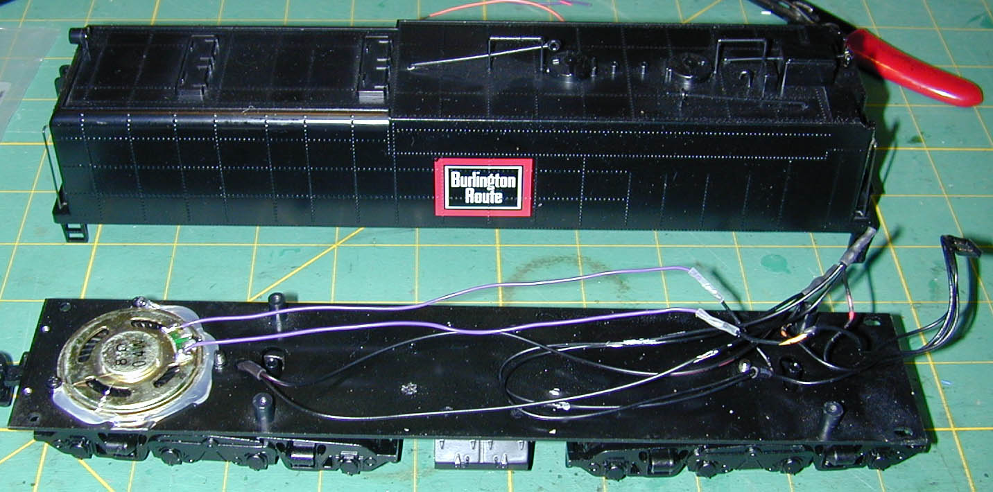
In the tender, mount the speaker. This tender already had in in it. Cut the wires that go to the outside pins on the plug, and connect them to the speaker. The two inside pins of the plug remain connected to the pickups on the wheels. That's it!
Here's the programming I used:
| Short Address | 3 |
| Long Address | 2923 (Locomotive Road Number) |
| CV 3 | 40 Acceleration Delay |
| CV 4 | 30 Deceleration delay |
| CV 34 | 65 Headlight stays on in reverse |
| CV 39 | 128 F5 Dim Headlight |
| CV 40 | 2 F6 Smoke On/Off |
| CV 41 | 128 F7 brake squeal |
| CV 49 | 143 Dyno light/LED (15 Dyno + 128 LED) |
| CV 61 | 139 Brake Rate |
| CV 112 | 128 Cam sync |
| CV 128 | 128 Master Volume |
| CV 198 | 18 Auto sound |
| CV 217 | 2 Eliminate run-aways |
Here is a video of the completed locomotive running on my test track.
